

Technical Primer: Why Shear Testing Matters
If you ask a contractor about anchor testing, they will usually describe a tensile pull test: a hydraulic ram pulling a bolt straight out of the wall to confirm it holds. It is the industry standard, the default verification method, and the test most teams know best.
But in complex engineering applications—especially seismic zones, heavy equipment installations, and edge-of-slab conditions—tensile capacity is only part of the story.
At Atlas Anchor Testing, we regularly encounter situations where the governing failure mode is not pullout. It is lateral failure: the anchor shearing, the concrete edge breaking out, or the assembly failing under side load.
In short: shear testing verifies how the anchor system performs when force moves sideways, not just outward.
The Physics: Tensile vs. Shear
To understand when shear testing is necessary, start with the force vector.
- Tensile Load (Pull): The force is applied parallel to the axis of the anchor. You are trying to extract the fastener directly from the substrate.
- Shear Load (Slide): The force is applied perpendicular to the axis of the anchor and parallel to the surface of the base material. You are trying to slide or slice the fastener sideways.
Tensile failure often appears as pullout or concrete cone breakout. Shear failure is typically more abrupt and may involve steel fracture, concrete pry-out, or concrete edge breakout.
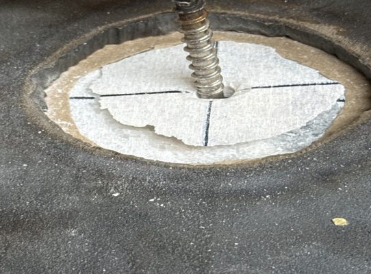
Typical Tensile Failure Mode
The image below shows a cone-shaped tensile breakout, where the anchor pulls out a portion of the surrounding substrate rather than failing laterally.
When Is Shear Testing Non-Negotiable?
While tensile testing may be sufficient for simple suspended loads or routine pullout verification, some scenarios require direct shear validation.
- Seismic Bracing & Lateral Loads
In seismic regions, anchors are subjected to significant lateral inertial forces as the structure sways. A pull test does not simulate this side-loading demand. - Heavy Equipment & Machinery
Generators, chillers, rotating equipment, and other vibrating systems create repeated lateral loading that can place shear capacity—not tensile pullout—at the center of the problem. - Wall-Mounted Structural Brackets
Brackets on vertical surfaces often support eccentric loads that translate into combined tension and shear. In many of these installations, the real-world failure mode is governed by side load or edge breakout.
Case Study: Plan B Engineering and the 20,000 lb Bracket
We collaborated with Plan B Engineering on a scaffold tie bracket project involving concrete screws installed along a complex profile where precast façade panels met at a corner.
System-Level Verification
- The Challenge: Testing individual anchors would not capture the behavior of the bracket assembly as a whole.
- The Solution: Atlas designed and built a custom test rig on-site.
- The Test: The full mounted bracket assembly was loaded in combined shear and tension to replicate the actual load path.
- The Result: The assembly was successfully taken to 20,000 lbs.
This is the difference between checking a component and verifying the installed system.
The Edge Distance Danger Zone
One of the biggest threats to shear performance is edge distance.
If an anchor is installed too close to the edge of a concrete slab or wall, the concrete between the anchor and the free edge may fail before the steel reaches its expected capacity. Instead of a stable load path, the system experiences concrete edge breakout.
- Tensile tests do not reliably expose this weakness. An anchor can show strong pullout resistance and still fail at a much lower lateral load because of edge proximity.
- The implication: Curtain wall anchors, balcony railings, façade supports, and edge-of-slab brackets often require dedicated shear verification.
Testing Standards: ASTM E488
ASTM E488 remains one of the core standards for evaluating anchor behavior in both tension and shear.
For a valid shear test, the load must be applied:
- Without friction acting as unintended support.
- With a loading configuration that does not artificially bend the anchor unless bending is part of the test design.
- With rigorous measurement of displacement as load increases.
Shear Test Setup
The image below shows a representative shear test setup used to apply lateral load and record anchor response under controlled conditions.
Conclusion
If your project involves seismic bracing, heavy lateral loading, machinery vibration, wall-mounted brackets, or edge-of-slab conditions, a standard pull test may not be enough.
You need to know how the anchor behaves when the demand shifts sideways.
Proper shear verification does not just confirm whether hardware remains in place—it reveals how the anchor, substrate, and connection behave together under realistic lateral force.
Need a Custom Shear Test?
Atlas Anchor Testing specializes in complex anchor testing, custom rigging, and verification protocols for conditions that standard pull tests cannot fully evaluate.
Need engineering-grade shear verification?
Contact Atlas Anchor Testing to develop the right test setup for your anchor system, substrate, and load path.